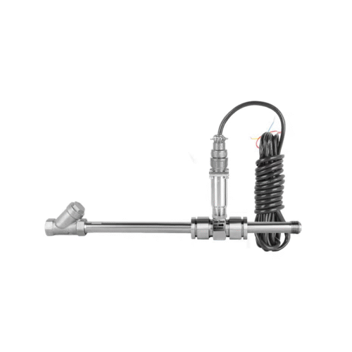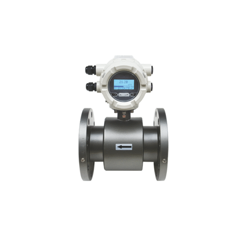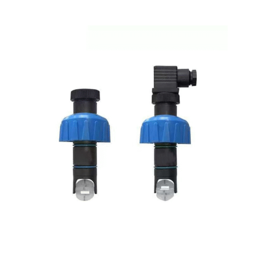


 An insertion electromagnetic flow meter consists of an insertion sensor and a converter. The sensor consists of an insertion rod, electrodes, excitation coil, ball valve, and sealing flange. The converter, which includes an internal circuit board and a converter housing, amplifies, processes, and calculates flow signals to display instantaneous and accumulated flow rates, and can output pulses, analog currents, and other signals for fluid flow measurement and control.
Principle
A small electromagnetic flow sensor is inserted into the measured pipe using a connecting rod at a specified location. The conductive fluid flows perpendicularly through the sensor’s operating magnetic field, which is equivalent to the conductor cutting magnetic lines of force in the magnetic field. According to Faraday’s law of electromagnetic induction, an induced electromotive force (EMF) is generated at both ends of the conductor. This induced EMF is detected by a pair of electrodes in contact with the fluid. The magnitude of the EMF (Electromotive force) is proportional to the average flow velocity (V) of the conductive medium, the magnetic induction intensity (B) of the magnetic field, and the distance between the two electrodes. Through computational processing, the flow rate of the medium can be calculated.
E=KBVD
In the formula:
E-induced potential;
K-Coefficient related to magnetic field distribution and axial length;
B-Magnetic induction intensity;
V-average flow velocity of conductive liquid;
D-electrode spacing;(Measuring the inner diameter of the tube).
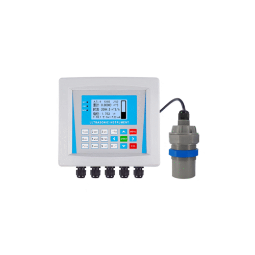
The sensor uses the induced potential E as a flow signal, which is transmitted to the converter. After amplification, transformation, filtering, and a series of digital processing, the instantaneous and cumulative flow rates are displayed on a back-lit dot matrix LCD. The converter has 4-20mA output, alarm output, and frequency output, and is equipped with communication interfaces such as RS-485, and supports HART and MODBUS protocols.